Lisa
Marketing department
Tel:+86-755-27252129
Fax:+86-755-27864271
ADD: B3 BUILDING, LANTIAN TECHNOLOGY PARK, SHAJING TOWN, SHENZHEN CITY, CHINA.
Plastic Injection Molding Part Design Guidelines
Our company has provided these plastic part design guidelines because we strive to produce your molds and parts perfectly according to your designs. In order to assure that your parts are moldable, please examine the basic guidelines laid out on this page and follow these basic design steps when designing your plastic parts.
Wall Thickness by Resin Material Guidelines
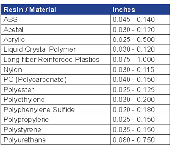
The proper material selection and observing uniform wall thickness in injection molded plastic parts, helps avoid potential issues such as sink marks and warpage. We recommended using the plastic part design guidelines in the table to the right as thicknesses vary by material:
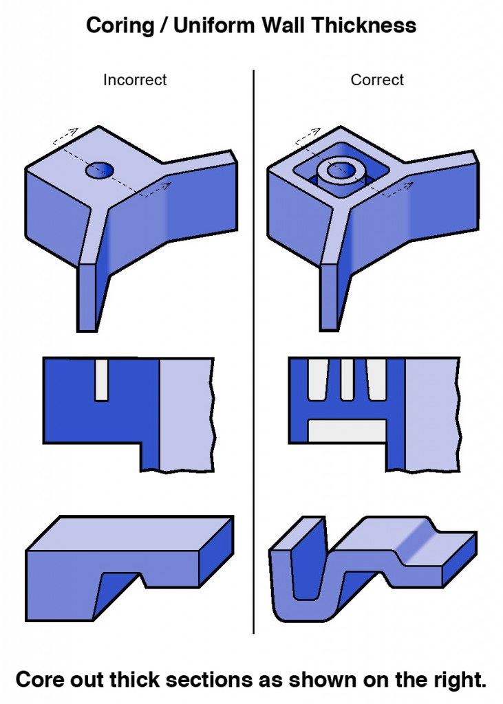
Core or redesign thick areas to create a more uniform wall thickness to prevent sink or voids.
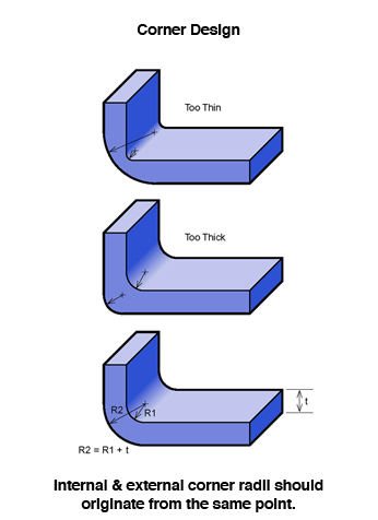
Making the outside radius one wallthickness larger than the inside radius will maintain constant wall thickness through corners. R2 = R1 + t
Rounding or tapering thickness transitions will minimize read-through and possible blush or gloss differences. Additionally, blending reduces molded-in stresses and stress concentration associated with abrupt changes in thickness.
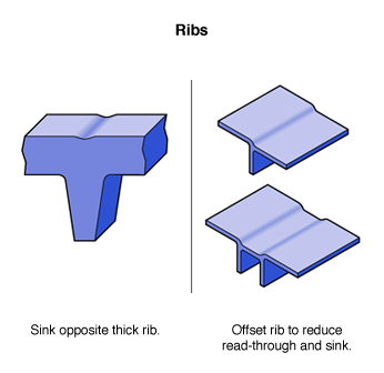
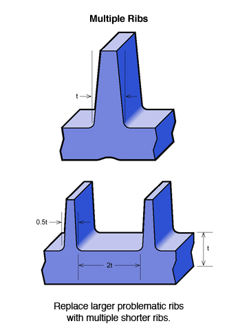
Ribs
Ribs provide a means to augment strength and stiffness in molded parts without increasing overall wall thickness. Other uses for ribs are as follows:
• Act as stops or guides for mechanisms.
• Ribs locate and captivate components of an assembly.
• They provide alignment in mating parts.
Proper rib design involves five main issues: thickness, height, location, quantity, and moldability.
Rib Thickness
There are many factors that determine the appropriate rib thickness. Thick ribs often cause sink and cosmetic problems on the opposite surface of the wall to which they are attached. The material, rib thickness, surface texture, color, proximity to a gate, and a variety of processing conditions determine the severity of sink. The illustration (right) gives plastic part design guidelines for rib thickness for a variety of materials. These guidelines are based upon subjective observations under common conditions and pertain to the thickness at the base of the rib. Highly glossy, critical surfaces may require thinner ribs.
Rib Location & Quantity
The location and quantity of ribs is vital in avoiding exacerbating problems the ribs were intended to correct— e.g., ribs added to increase part strength and prevent breakage may reduce the ability of the part to absorb impacts without failure. Furthermore, a grid of ribs added to ensure part flatness may lead to mold-cooling difficulties and warpage. Typically much easier to add than remove, ribs should be applied sparingly in the original design and added as needed to fine tune performance.
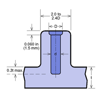
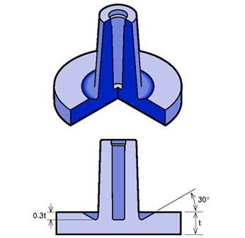
Bosses find use in many part designs as points for attachment and assembly. The most common variety consists of cylindrical projections with holes designed to receive screws, threaded inserts, or other types of fastening hardware. Generally, the outside diameter of bosses should remain within 2.0 to 2.4 times the outside diameter of the screw or insert
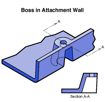
It is suggested avoiding bosses that merge into sidewalls because they can form thick sections that lead to sink. Proper bosses should be positioned away from the sidewall, and if needed, use connecting ribs for support. Try using open boss designs for bosses near a standing wall.
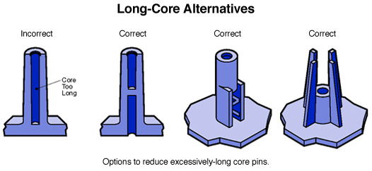
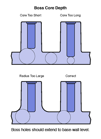
Normally, the boss hole should extend to the base-wall level, even if the full depth is not needed for assembly. Shallower holes can leave thick sections, resulting in sink. Deeper holes reduce the base wall thickness, leading to filling problems, knit lines, or surface blemishes. Because of the required draft, tall bosses (those greater than five times their outside diameter) can create a filling problem at their top or a thick section at their base.
Draft (Draft Angles)
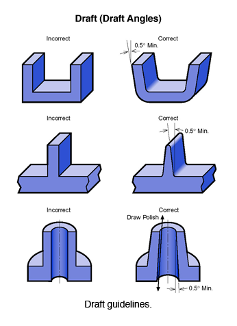
Draft: Providing angles or tapers on product features such as walls, ribs, posts, and bosses that lie parallel to the direction of release from the mold which eases part ejection. How a specific feature is formed in a mold determines the type of draft needed. Features formed by blind holes or pockets (such as most bosses, ribs, and posts) should taper thinner as they extend into the mold. Surfaces formed by slides may not need draft if the steel separates from the surface before ejection. Other guidelines for designing draft include:
• Draft all surfaces parallel to the direction of mold separation.
• Angle walls and other attributes that are formed in both mold halves to assist ejection and retain uniform wall thickness.
• As a general rule, use the standard one degree of draft plus one additional degree of draft for every 0.001 inch of texture depth.
• Use a draft angle of at least one-half degree for most materials. Design permitting, use one degree of draft for easy part ejection. SAN resins typically require one to two degrees of draft.
